

Liftoplane performs in-flight turns by using a different handling of the rotors of the respective sides. This method of doing turns doesn’t employ the different rotation of the rotors, since the shafts of both rotors are connected together for redundancy, and since turns should be permitted also in the case of pure gliding with the rotors locked against rotation.
This operation is similar to a coordinated turn on an airplane or glider. Its introduction also begins from a roll inside of the target turn. But, the roll on an airplane is performed by ailerons, which have an adverse effect on the turn by posing horizontal acceleration in the wrong direction due to the adverse drag distribution. And so, the airplane begins counter rotation in the event that nothing is done. And therefore, to prevent this, two features are used. The main feature is an increasing the pitch by using the elevator, which leads to an increasing the lift and the flight path curvature consequently. And, since the plan of such a curvature is inclined correspondingly with the existed roll, the inertial vertical of the introduced curvature is also inclining, introducing a rotation in the right direction. Also, a correctly performed coordinated turn prevents the airplane from slipping. An additional feature here is the action of the rudder, which enforces the beginning of the rotation.
But for the liftoplane, there is avoidance for the adverse back-rotation effect upon introducing a turn, for all powered operations. Also, for pure gliding, the adverse effect is weak, and the rudder is used to speed up turn entry.
Some experimentation during the flight simulation was used to obtain the correct parameters of handling for different flight operations. This flight simulation was only 2-dimensional. So, each side of the aircraft in the turn was modeled in separate experiments. A correct balance of the components of accelerations was used as a criteria for the correct turn entry.
This result for turns in the various straight line flight operations is represented below.
1: Getting initial altitude and speed at 12m
2: Getting cruise speed in ascent at 75m
3: Ascending to cruise altitude at 3900m
6: Recuperative descent at altitude 600m
7: Dropping the speed at altitude 82m
8: Dropping the speed and the descent rate at altitude 6m
This result shows the deviations of the acceleration vectors normalized by “g” for the respective pitchings of the wings controlled by using the respective deviations of the opposite and main values of the biangular handling reflected in the corresponding deviations of the pitch and gain components of the respective PGS-states.
There are eight operations that cover the full spectrum of the entire flight. They can be divided into three categories.
The first is a category of normal turns. I referenced it as normal because it includes the cruise operation itself. For the normal category, the turn is introduced by applying a positive difference in the outside relative to the inside for the MA deviations and the corresponding halved negative difference for the OA deviations. These deviations are presented in separate columns for OA, MA, and related P and G. And, the last column represents the deviations of the accelerations themselves. The normal category includes the first four operations from the low-speed ascending flight up to the cruise. Also, the ratio between the horizontal and vertical components of the induced acceleration varies, so for some operations the roll may be too high relative to the rotation. In this case, additional handling may be required to increase the common lift to enforce the coordinated turn. And after entering a coordinated turn, only the additional control of the increase in lift should be kept, as all airplanes do. But in any case, all variants, listed in the table, avoid the adverse back rotation, featured for the ailerons of an airplane.
The second category contains only the gliding flight itself, and this is the case of neutral turns. For this case, the horizontal rotation is near to zero. This is enough to perform this rotation by the handling for an additional lift in a coordinated turn, but that can be less effective than in a normal case. And so, a rudder can speed up that turn. For this category, only a small difference in MAs is required to enter in a turn. And the direction of this difference is the same as for the normal category.
The third category contains all remained operations, and this is the case of inverted turns, since the direction of the handled controls here is opposite to the direction of normal turns. But they have some differences. The first two operations here are the recuperative descents with different levels of the recuperated power. Both the operations use the same magnitudes of the differences applied to MAs and OAs as compared to the normal category. But the operation with higher power has a much higher rate of the horizontal rotation. The third operation is a low altitude part of the landing sequence, where the turns are difficult, due to the risk of slipping during the roll during the introduction the turn. But there is a possibility to perform a flat turn without a roll at all. In this case, the magnitude of the difference between MAs should be two times more than the magnitude of the related handling for OAs.
Using such differed categories of handling a turn can be problematic for the pilot. But this can be resolved using the flight computer, which interprets the movement of the joystick into corresponding changes in the parameters of the biangular handling and the PGS-state for the rotors on both sides, dependently on the current operational state related with a particular category. Also, for almost all operations, a rule of thumb can be used: “The magnitude of the gain for the inside should be greater than for the outside”. The operation 8 is an exclusion from this rule, but this can be explained by the high stall condition developed on the wings of the rotors.
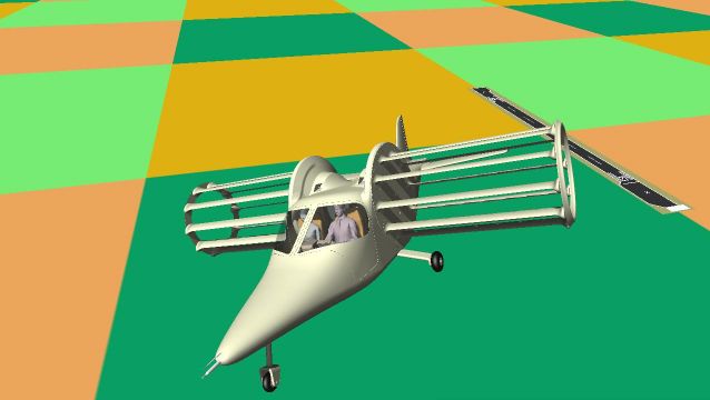
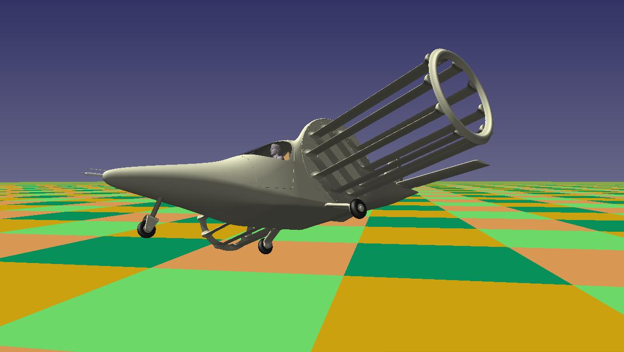
The images at the beginning and the end of the topic picture the liftoplane in the right turn upon gaining of altitude. They show the pitching of the wings, expressed in the difference between the inner and outer gains of the rotors. But this difference is somewhat exaggerated for the purpose of explanation.

Copyright © 2018-2023 Yuri Feldman - All Rights Reserved