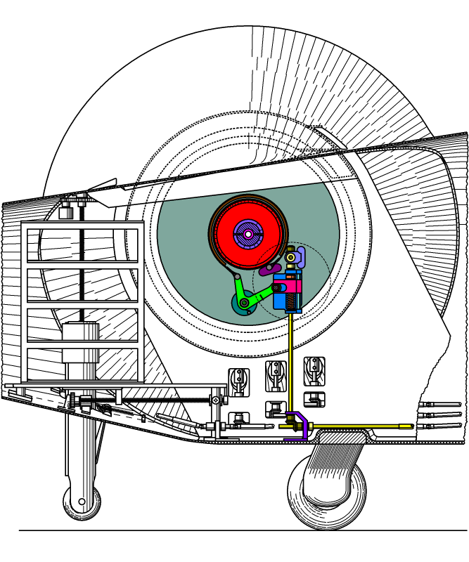

††Handling of the liftoplane upon pure gliding requires locking both rotors from rotation. This action is performed using a locking system. The main parts of the locking system are shown in the chart below.

† The chart shows an inner lateral view of the left side of the aircraft. It depicts in colors all the relevant and related elements of the locking system. A locker is the main part of the locking system. It is mounted on the engine depicted in the light teal color. The entire locker is kind of a band brake, which is used on some bicycles, but adapted to have a precise control. A lockerís drum of the red color is mounted on a setup flange of some hollow shaft not shown, which is used to accept and clamp the central shaft (of the magenta color) of the detachable rotor. Also, a central coupler of the light violet color that connects the both sides' central shafts together is pictured here. A locker's band with a frictional lining of the brown color goes along the perimeter of the drum at a certain distance when the locker is in the unlocked state. The next chart shows a detailed view of the circular area pictured in the chart above.

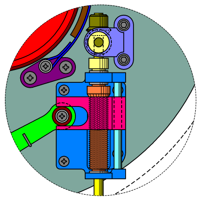
† One end of the band of the blue color is dressed on an axle on the base of the dark magenta color, which is mounted on the engine's lid. The other end of the band is pivotally fixed on the end of a pull lever of the green color. The pull lever is fixed to its shaft and can rotate relative to its base of the teal color, which is mounted on the engine's lid. A groove follower of the dark red color is rotationally mounted on another side of the lever. A main bracket of the light blue color is mounted on the engine's lid. A screw of the orange color is fixed on an outer locking shaft of the yellow color. A threaded lead of the pink color can move in the vertical direction during rotation of the screw inside it. A guide rod of the cyan color is fixed on the main bracket parallel to the screw and is inserted into the corresponding hole of the threaded lead, additionally aligning it during its movement. The threaded lead has a slot or groove in which the groove follower of the pull lever is placed, and can be moved in the horizontal direction. Also, the threaded lead has a thin slot from the direction of the pull lever, which corresponds to the thickness of this lever for an additional aligning of the lever.
† Rotation of the outer locking shaft permits precision control of the lock state of the left side rotor. A miter gear of the dark yellow color is fixed on the upper end of the outer locking shaft and is oriented to down. It is used to link with the right side rotor's locker, and on the right side, it is placed in opposite bottom place. A link bracket of the sky color is mounted on the engine's lid and provides a support for a side linking shaft of the yellow color. Another miter gear, which is depicted by the dashed circle, is fixed on the inner end of the side linking shaft and is meshed with the first miter gear. Both sides linking shafts are connected together by a central linking shaft not shown, using respective couplings. The last connectivity is used for easy setup of the entire locker link.
† Looking at the first chart, a lock gears bracket of the violet color is mounted on the floor of the fuselage. The end of the outer locking shaft enters to the lock gears bracket from the top and has a support there. A bottom miter gear of the dark yellow color is fixed on the end of the outer locking shaft and is meshed with another miter gear, which is fixed on a primary lock shaft of the yellow color, which also has a support in the lock gears bracket. The primary lock shaft is directed toward the cockpit.
† Control of the lock state is performed by a special Lock-trimmer (L-trimmer), which is also part of the cockpit control and instrumentation. The unit of values for the L-trimmer is percent. Its zero value corresponds to the state, when the bands of the lockers touch by their frictional linings the related drums. The range of the lock state is from -20% to 100%. Manual control of this trimmer mainly services the emergency cases. Normally this trimmer is under a computer management. A special servo is mechanically connected to this trimmer, as well as a special encoder. The encoder reports its value to the central computer.
† A special L-button on the control panel of the cockpit it used to perform a respective command by the central computer. The actual locking has a condition required both the winding speeds WST and WSA to be very near to zero. So, this command initiates zeroing the WST with a speed of the natural rotation of the servo of the WST-trimmer. On the other hand, the departing the WST value from zero by using a respective command through the computer management initiates an unlocking command in advance. All that permits a simple management of the lock state and the winding speed on the pilot's side.
Copyright © 2018-2023 Yuri Feldman - All Rights Reserved