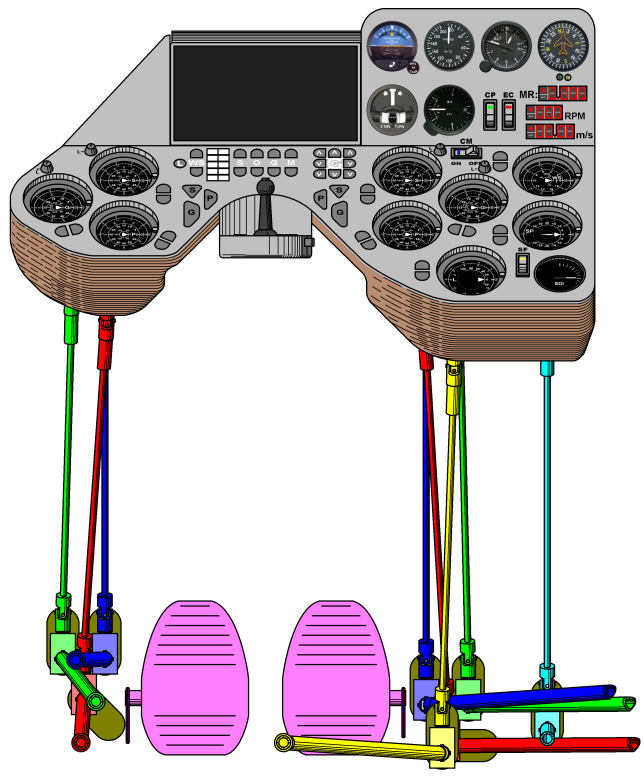

The cockpit of the liftoplane has the controls and instrumentation necessary for the pilot for handling it. The chart below shows an overall view of the cockpit with respective transmissions for managing all principal mechanical components of this aircraft.

The cockpit acquires control of the PGS-states of both rotors, the pitch of the stabilators and the lock state through the respective secondary shafts, which are connected to the respective primary shafts of these mechanical domains by respective universal joints, respectively. Two sets of such secondary shafts for the PGS-states are depicted below in the respective red, green and blue colors and connect the primary shafts of the PGS gearboxes to the respective diverters depicted in the same but light colors, respectively. Also, the primary shafts of the left side PGS gearbox are depicted here in the sectional view. Similarly, the secondary shafts for the stabilators pitch control and the lock control are connected to the similar diverters and are depicted in the cyan and yellow colors, respectively.
Each diverter has inside a pair of meshed miter gears on shafts with the respective horizontal and vertical universal joints on the outside. Vertical linking shafts have a smaller diameter than the secondary shafts, connecting these diverters to the corresponding upper universal joints that are mounted on the exit shafts of the respective trimmers. The inner shaft of each horizontal universal joint passes through its diverter and is rotatably connected to a related encoder of the dark yellow color mounted on the diverter or fuselage.
A left and a right pedal of the light magenta color are placed under the cockpit and are connected by respective wires of the magenta colors to the rudder. Some pulleys are used to conduct these wires. The connectivity and use of the rudder pedals are the same as for a conventional airplane.

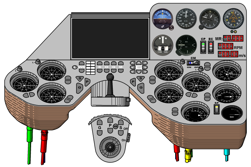
The chart above pictures the cockpit. Also, a joystick pad of this cockpit is pictured here in the center, in an upper view. The cockpit has two main domains: an indicator panel, which has generally a vertical orientation, and a control panel, which is tilted by about 45 degrees. A display of a central computer is placed on the indicator panel under an anti-glare guard and is inclined on a pivot toward this guard at some angle. A CP-switch with the green LED is placed on the indicator panel and is used to manage the power state of the components of the Control Panel. An EC-switch with the red LED is placed on the indicator panel and is used to manage the power state of an Engine Controller. Three red-LEDs segmented digital indicators are located in the lower right corner of the indicator panel and are managed by the Engine Controller. From bottom to top they are: a WSA-indicator that is used to indicate the actual winding speed of the rotors, an RPM-indicator that is used to indicate of the RPM of the rotors, and an MR-indicator that is used for indication of the Moment Ratio (external) on the common powering shaft of both rotors.
A CM-switch with the blue LED is placed on the upper side of the control panel and is used to enable the Computer Management over all trimmers of the control panel. An SF-switch with the yellow LED is placed on the right lower side of the control panel and is used to enable the automatic Stream Following mode by using the operation of the stabilators from the side of a stabilator controller.
The control panel contains a number of trimmers, which are used for control and indication of the controllable mechanical features of the aircraft. These features include: the each side PGS-state, the target winding speed (WST) of the rotors, the stabilator pitch (SP) and the lock state of the rotors. These trimmers are mounted under the control panel and are closed by a cover of the coffee color along the sides of the control panel and their bottoms, together with the other elements of the control panel. The trimmers for the PGS-state are placed symmetrically for the pilot. The Pitch-trimmers are placed on the inner lower part of the left and right sides. The Skew-trimmers are placed on the inner upper part of the left and right sides. The Gain-trimmers are placed on the outer, middle part of the height of the left and right sides. The meaning of this placement for the Gain-trimmers is to reflect the maximal impact of the gain change on the turns operations. The WST-trimmer is placed on the right side under the WSA-indicator. The SP-trimmer is placed at a middle height of the right side above the SF-switch, which turning on inserts the SP-trimmer into the automatic controlled loop. Also, here is a Stream Deviation Indicator (SDI), under the SP-trimmer, which can assist in the case of a manual handling of the SP-trimmer or can be used to indicate the efficiency of the automatic controlled loop. A Lock-trimmer is placed on the remained bottom medial right side. The manual handling of each trimmer is allowed by a retractable handle, which can directly rotate the face side of the trimmer. Exactly the same rotation of the face side of each trimmer with its handle is performed in case of non-manual handling. So, the face side of each trimmer is located under the face level of the control panel, including also the handle. This resolves a possible obstruction problem for the pilot, since the self-rotating of the handle over the level of the control panel can be dangerous.
The handling value of each trimmer can be changed by using a pair of buttons close to it, where the lower button is used to decrease this value with some speed, and the upper button is used to increase it with the same speed. The orientation of the buttons for changing the pitch and gain isn't vertical. Their inclinations reflect the impact of the related feature on the turns operations during the normal turn mode, which includes the cruise. This impact is moderate for the pitch and high for the gain. Also, the directions of these inclinations reflect the normal turn mode. For example, the inclination of the left gain buttons hints: "press the leftmost button of the left gain to turn to left". Also, this turn action should be accompanied by pressing the opposite button of the other side gain, pointing for this example to "the leftmost of the right gain" button.
The gain and skew trimmers must have abilities for the strict handling, as it was mentioned upon describing the SG-compensator. So they have special locking knobs of the gray color on their upper outer sides. In the case of the computer-managed handling, the impact of these locking knobs is irrelevant. But, in the case of the manual handling, the locking knob of each required to be locked trimmer should be rotated to a locking position, which is indicated by the letter "L" near a tick of the exact position. And, in case of non-manual handling without the computer management, any locking knob should be in the locking position, it will be unlocked automatically. Also, each locking knob fixes its normal or locking position with some force, but it doesn't fix its intermediate position.
A joystick pad is mounted some below the upper level of the control panel on its concave support, which corresponds to the central concave rim of the control panel. It has a joystick of the dark gray color mounted in its center and other controls. Three pairs of the buttons of common controls of the gray color are placed in forward of the joystick. These pairs control: the common pitch with the P-letter, the common gain with the G-letter and the common skew with the S-letter. Here, the upper buttons increase the related values for both rotors, and the lower buttons decrease them. An HS-button is placed between the pairs of the common pitch and common skew buttons. When the button is pressed, the both side trimmers of the pitch and skew will be operated with a High Speed of change if appropriate change commands are presented. This high-speed feature is required during the beginning and finalizing the aerial braking on the runway, when the pitch and the skew are drastically changed simultaneously. An S->P-switch of the gray color is placed on the right side wall of the pad. It enables for the pitch-trimmers to follow with the same speed and direction after the changes of the skew-trimmers, so only the common skew buttons can be used. This feature services all runway operations, and also was referenced as a "propelling" mode.
The buttons for side based differential operations are placed on respective sides of the central symmetry line of the control panel. These differential buttons of the gray color are: the P-buttons, the G-buttons and the S-buttons. Pressing of each of these buttons will decrease the related value on the side where the button was pressed, and increase the related value on the other side. The decreasing was selected, because decreased values for the pitch and gain are required for the inner side of the normal mode turn. The P-buttons and the G-buttons service the turns operations in a more convenient way than the paired buttons of the trimmers. And, the S-buttons are placed here for completeness. All these buttons reflect their "decreasing" action by having a shape with a narrowed end below. Additionally, the P-buttons and the G-buttons have a side-pointing shift of the lower end and an increased high those reflect their impact on the turns ability.
Prior to this point, all described handling buttons were designed for operation over trimmers without using the computer-managed handling, i.e. the CM-switch should be in the "OFF" position for that. In this mode, only a simple electromechanical logic is used for their respective variations. This provides an additional level of redundancy, in addition to the computer-managed handling. And, the manual handling of the trimmers is the third, lowest level of redundancy. This architecture was selected, because the presented aircraft is experimental, and all tiers of its entire handling pipeline must be researched and optimized. But, for the end user aircraft, some redundancy levels can be simplified or eliminated, leaving a more simplified aircraft handling interface, like as the only components of the computer-managed handling.

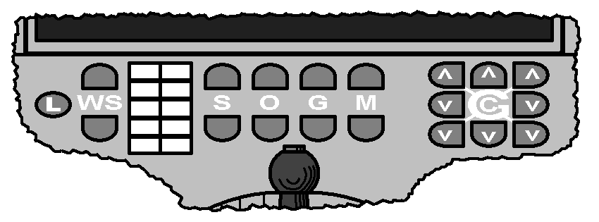
Elements of the computer-managed handling with the white marking are placed directly under the display (see the picture above) and additionally include the joystick with a capture button of the gray color on its top. This capture button is used to enable the joystick and store its initial position with the initial values of controlled features as a reference point for handling further deviations of the joystick from this initial position. And so, the handling of this aircraft with the joystick is generally variational, which permits to accommodate very wide operative ranges of handling features, maintaining a high variation accuracy for particular operations, for the pilot friendly convenient handling. For a simplest use of this handling, computer can sophisticatedly interpret the spatial motion of the joystick for the spatial and kinematic evolution of the aircraft. Also, the kinds of such interpretation can be flexible parameterized and selected on demand of the pilot for the different operations.
A pad of the common handling is placed in the center under the display and has four pairs of buttons, where the upper buttons increase respective values and the lower buttons decrease them. Here, S-buttons manage the skew, O-buttons manage the opposite value of the biangular control, M-buttons manage the main value of the biangular control and G-buttons manage the difference between the main and opposite values of the biangular control, the variations of which at low gain in the pitch-mode of the biangular control are very close to the variations of the gain of the PGS-state. So, this parameter can be considered as a high-level gain or biangular gain, and the G-buttons are placed between the O-buttons and the M-buttons to reflect their differential nature. All these SOGM-buttons manage the respective parameters for the rotors on both sides simultaneously, which is reflected in the word "common" in the name of this pad.
A pad of the in turn handling is placed on the right side from the pad of the common handling. It has in its center a C-letter inside of a G-letter. The G-letter is connected by diagonal lines to the buttons in four corners of this pad. These corner buttons are used to manage biangular gain, similar to those G-buttons. Here, the bottom corner buttons decrease the biangular gain value for the side where this button was pressed and simultaneously increase this value for the opposite side. These bottom corner buttons are used in the normal mode of the turns operations. The variations of the biangular gain for turns on the cruise operation can be simply deduced looking at the respective table. They have the same sign as the variations of the gain of the PGS-states and are a bit higher. And so, the logic for turns that use biangular gain is the same as for low-level gain. This is also reflected in the down directed arrow signs pictured on the lower corner buttons. The upper corner buttons are used in the case of inverted mode of turns, which is applicable for much of operations during descent of this aircraft. Some kind of a high-level pitch can be defined for the biangular mode, like as it was introduced for the high-level gain. It will be simply an average value of the opposite and main angle. But, I don't use the word "pitch" for this parameter. It is better to use the word "collective" for each side rotor, like it is used for the rotor of a helicopter, since the word has more universal meaning for both modes of biangular handling, like as the word "gain". So, the C-letter in the center of this pad hints to the word "collective", like the G-letter hints to the word "gain". The buttons on the center of the side of this pad are used to decrease the collective angle of the rotor on the side where the button was pressed and to increase on the opposite side, and it is reflected in the down directed signs of arrow pictured on them. This is OK for the normal mode of turns, but for the inverted mode, other buttons are required here for the intuitive handling, similar to the upper corner buttons used for gain. Such buttons can be added to each respective side of this pad, but there is another way for this intuitive handling. Instead of looking for the opposite direction buttons, which yet require some switch in thinking, better is to begin thinking about the normal mode of turns as be managed by inside turn controls, and about the inverted mode of turns as be managed by outside turn controls. So, the buttons on the lower corner and the center of the side of this pad from the out turn side can be used to initiate such a turn. The center upper button on this pad increases the collective angles for both rotors simultaneously, and it can be used to assist in a coordinated turn, reducing inner slip in the turn when entering the turn. Similarly, the center bottom button on this pad decreases the collective angles for both rotors simultaneously, and it can be used to assist in a coordinated turn, balancing against having an outer slip and to exit a turn. These two vertical buttons of this pad can also be used without a connection with a turn. They can be considered as a complement to the four common handling pairs of buttons of the common handling pad as the fifth pair of C-buttons for the common handling of collective angles.
The pair of WS-buttons is simply a computer processing equivalent of the pair of WST buttons near the trimmer, which is placed in a more convenient place. The L-button is simply a button for a lock command. Without this button, the lock of the rotors will be performed when two conditions will be met altogether. The first condition is the presence of the WST equal to zero (with some error range, of course). The second condition is the presence of the magnitude of the actual winding speed (WSA) below some threshold. And, the L-button only sends a command to reset the WST value with a speed of the natural rotation of the servo of the WST-trimmer. This finite speed of rotation of the WST-trimmer additionally prevents to perform a too fast lock, which can induce a very high moment on the common shaft of the rotors and on related elements. Also, the use of the WS-buttons is subject to this WST change rate limitation.
The extended command pad of the white color is used to select particular commands by the pilot. They can include particular customizations of the control buttons and joystick for particular flight operations, any switches for display's representations or any other commands. Also, the display can be touch-sensitive.
The indicator panel has also standard instruments, which can assist the information on the display or can be used independently, especially as standby instruments. These instruments currently selected as (from left to right and from top to bottom): an Attitude Indicator (AI), an AirSpeed Indicator (ASI), an altimeter, a compass, a Turn and Slip Indicator (TSI) and a Vertical Speed Indicator (VSI). The indicated speed (IAS) of the airspeed indicator will be proportional to the LAS normalized by the specific stagnation speed that compensates for changes in density of air. And so, the airspeed indicator well suits for the standby instrument to control this aircraft.
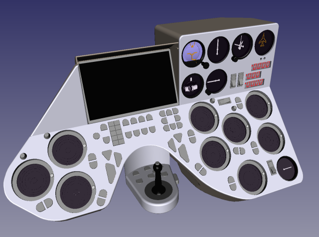
The image below shows a CAD rendered view of the cockpit without the markup.

Copyright © 2018-2023 Yuri Feldman - All Rights Reserved