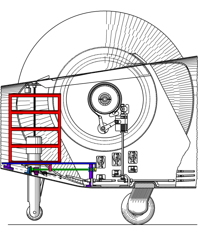

Having a correct position of the center of gravity (CG) can greatly impact on the operating range of the "stream following" system on the basis of the moment ratio (MR). The following system, shown in the chart below, provides a possibility to adjust the CG.

The chart shows an inner lateral view of the left side of the aircraft. It depicts in colors all the relevant and related elements of the CG adjusting system. The main part of accumulators of the aircraft is placed on two racks on each side of the aircraft. The left rack is depicted here in the red color. The accumulators are fixed on the shelves of this rack, but they aren't shown here. Additionally, the aircraft has a place for accumulators in its forward compartment along the forward walls. This position of the nose accumulators permits to shift the center of gravity to forward, which is desirable, since it will decrease the moment compensating force provided by the stabilators operating in a partial downwash. On the main side, each accumulator rack can be moved in flight or before that in the longitudinal direction. This allows to alleviate the moment changing due to the variability of the aircraft's load. This variability includes variation in the weight of the pilot and passenger, and also the action of the undercarriage wheels on the runway. All that requires a correction of the CG for fitting to an optimal operating range of the stabilators from takeoff to cruise with respect to the overall performance.
The accumulator rack is placed on two saddles of the blue color that are placed relative the axis of the rotor in a position that allows the rack to be very close to the elements of the rotor's locker without obstruction while sliding on the saddles. The saddles are mounted on aft supports and forward supports of the violet color, which are fixed to the fuselage. A bottom sliding plate of the orange color is fixed to the rack and secures it from falling out from the saddles. A threaded rib of the pink color is mounted on the forward end of the bottom sliding plate. A long screw of the dark green color can move the rack while rotates. A forward support for the long screw of the cyan color is mounted between the pair of the forward supports and is fixed to them using screws of the gray color. An aft support for the long screw of the light blue color is attached to the inclined floor of the fuselage. A rack moving gear of the green color is fixed on the long screw near the aft support and is meshed with a rack moving pinion of a rack moving servo of the dark magenta color, mounted on the floor of the fuselage. A rack position encoder of the yellow color is rotatably connected at its entry to the shaft of the long screw protruded from the forward side of the screw's forward support and is mounted on the bottom side of one or both saddles.
The movable rack for accumulators can be optionally modified to have only three shelves in the vertical direction, lowering the center of gravity, but be two times longer, since this is permitted by the clearance. In this case, it can be 40 percent thinner in the axial direction, increasing the cargo space between the rotors. Also, the longitudinal movement can be increased to better alleviate the moment issue.
A control panel of the accumulator racks is placed in the cockpit area and manages the longitudinal position of these racks using the servo and the encoder of the left and right racks. Additionally, the racks' control panel is connected to the central computer for more convenient management.
Copyright © 2018-2023 Yuri Feldman - All Rights Reserved